BY AN AMATEUR
The Hartley Diamond Faceting Machine Modified.
By Larry W. Davis
 (tm)
(tm)
Due to the nature of the materials which are used in this project
and the speed which they operate;
the author must give warning that extreme danger is involved with
use of the equipment. I take no responsibility for anyone who makes
a copy of any part of this machine or the whole machine and then attempts
to sell or use it in any way.
I have simply tried to recreate an interesting machine from the past and in no way do I recommend that it be used. It is strictly an attempt at a machine shop project.
The completed lap assembly will weigh in at between 50 and 75 lb.. Running it at full speed will mean that you are turning an extreme mass at a very high speed.
The machine may operate in excess of 1,750 rpm. depending on the pulleys and other equipment the designer may decide to use. The cutting lap used is made of cast Iron which will crack if and when it will. It will scatter like shrapnel so the use of a safety lap is highly recommended and should even be required. There is one shown here.
If you take it upon yourself to make a copy of this machine fine. But if you use it you must have a DEATH WISH and you are entirely on your own. I will not use it myself. My copy has been stored and partly dismantled since the show where it was displayed.
L. D.
Very well made for the time and not having any commercial parts used
(such as the modifications which I have used) the Hartley machine worked
very well. I had the availability
of several spare parts from other machines which meant that I would
not have to make as many
parts for my version. There still would be no reason why the
original would not work.
Several of the diagrams appearing in the magazine were lacking in drafting practice and were very difficult to follow. One part which gave me fits figuring out was the indexing mechanism and dop quill. For this reason as with those in the above paragraph I decided to abandon the original and move on to another head which was available and would lend itself to modifying.
Here you will find a series of photographs which show how I have reconstructed the Hartley machine and modified it to use a modified RayTech Shaw facet head having a diamond holding claw and pivoting yoke assembly to replace the Hartley indexing head and claw assembly. This will allow the individual to adapt a readily available and well made commercial facet machine head .
The entire project was completed in a little over three months from the start at a cost of just under $1,000. Much of the more detailed and complex work was farmed out to a local machine shop and the modification of the RayTech head was completed by the author.
If anyone would like further details on how the machine was designed and a set of measurements please contact me at my e-mail address faceter@bigfoot.com
In all cases as I found the standard commercially used measurements for laps, spindle and bore holes to be very well designed and to passed stress requirements I have attempted to use the commercial size measurements.
No attempt has been made to show all of the details such as the mounting
slide rails which the head
moves on during adjustment. Details of this nature may vary
from person to person during construction and are considered personal preference
items.
The machine as shown here was exhibited at the Wichita Gem and Mineral show April 1989. After the show I did charge the lap with 50,000 grit diamond grit and olive oil.. I then took it home and cut two facets on a single broken 1 ct diamond. The faces were placed where the break was located and served to not only cover the break but show how well the lap would cut in areas of extreme roughness.
The machine will work if you want. You have to adjust for the grain direction in the diamond and will find many sparks flying off the lap along with a good deal of squealing and perhaps some new words coming from your own mouth when the sparks fly.
If I were on T.V. with my own Mechanical Whiz.. show I would rate this a 5 hammer (well perhaps 10 hammer) project. Making this machine in your own work shop will require you to have a lathe which will (with ease) swing a 13 to 14 inch dia. disc, a milling machine of good size, Drill press, Welding machine or gas welder (brazing), and have a very good machine shop technique as every step is critical and will only serve to make it work right. That will in turn make it a lot more fun to use. Not to mention keeping the local or state mental institution population a bit lower.

The author at right demonstrating the faceter to Mr. Roy Justice
at
the April 1989 Wichita Gem and Mineral show in Wichita, KS.

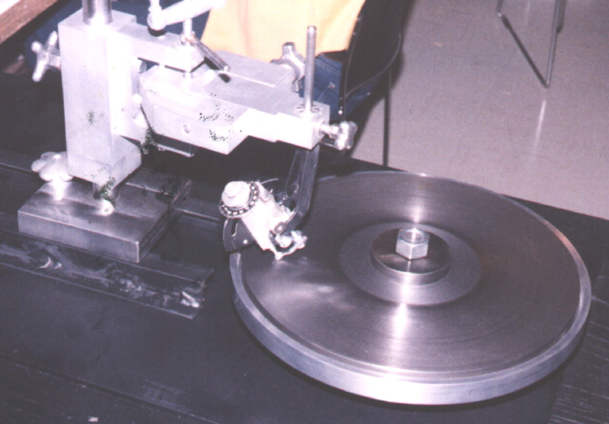
The mounted head and lap assembly with the head locked in the up
position.
Enlarge the view and you can see the grain direction indicator ring
at the base
of the quill. The handle with the two hand pieces was cast
by me from old beer cans
and some scrap metal that I had.
Information on casting your own Aluminum parts can be had by getting
a copy of the
Lindsay's Metal Working Books catalog and buying the series of books
by Dave and Vince Gingery. Catalog address: Lindsay
Publications Inc., PO Box 538,
Bradley IL 60915-0538, Phone (815) 935-5353. None of
the Gingery books cost more
than $9.95 and there is now an hour long video tape from Dave showing
shop technique.
The Gingery book series will take you from building a small scale foundry to melt the metal right on up to making very effective but less expensive machine shop tools. They will teach shop technique that will make your home shop efforts much easier.
This is the source book for all my home brew shop projects. Build from scrap and save.
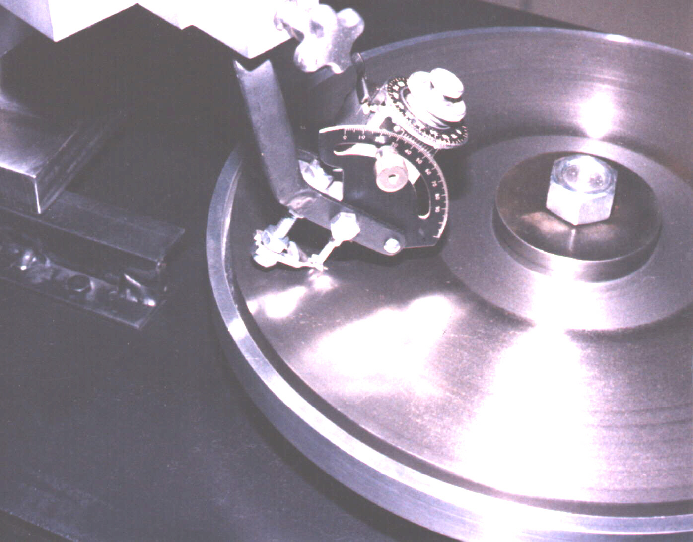
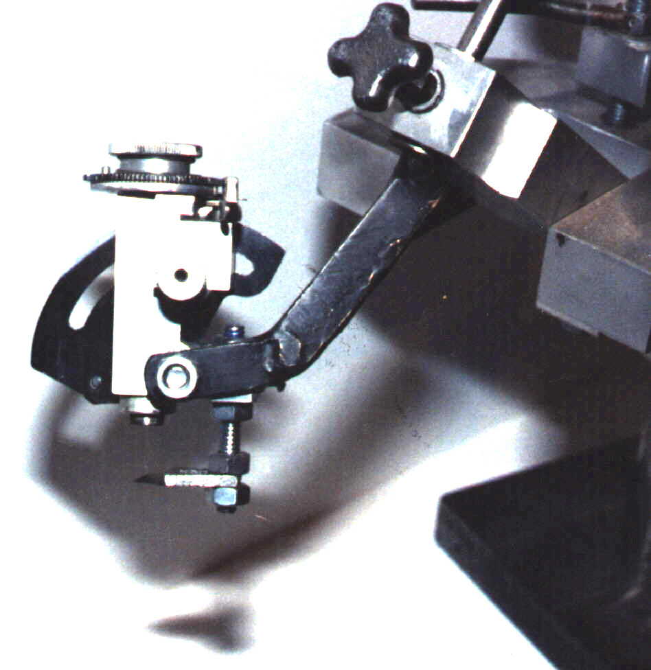
Close up of the modified RayTech head with diamond clamping claw
in place holding
a stone while cutting. In this case the stone was a CZ used
for demonstration purposes.
The lap is 12 inches in dia. and a finished 5/8 inch thick having a 22 mm dia spindle hole.
Shown under and surrounding the cutting lap is a safety lap consisting of a hogged out plate of Aluminum stock cut to allow just 1/8 inch of the cutting lap to protrude above the safety lap.
The entire assembly was balanced as well as possible. They
will run at an speed
near 2,900 rpm and will throw a good bit of wind out to 3 feet from
the laps.
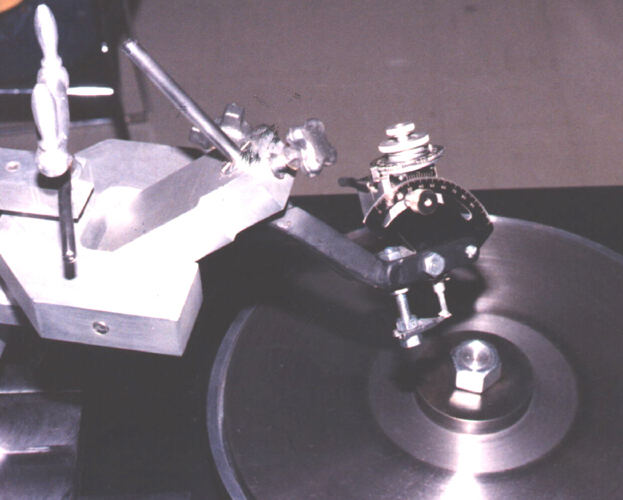
Head in cutting position on lap. Note that the position has
been changed
from other views. This is part of the "Grain" finding process.
The quill and
indexing head have been rotated about 180 from other views.
It will rotate
a full 360 degrees without any stop from where ever you start.
With care you can just begin to make out that the quill / yoke assy..
is made up of two
formed "U" brackets welded to each other as seen just above the
RayTech head. (the black assy. to which the RayTech head is attached).
Head shown in locked position "UP" for safety.
Note the height adjustment locking lever and nut just under
the double handle at upper left.
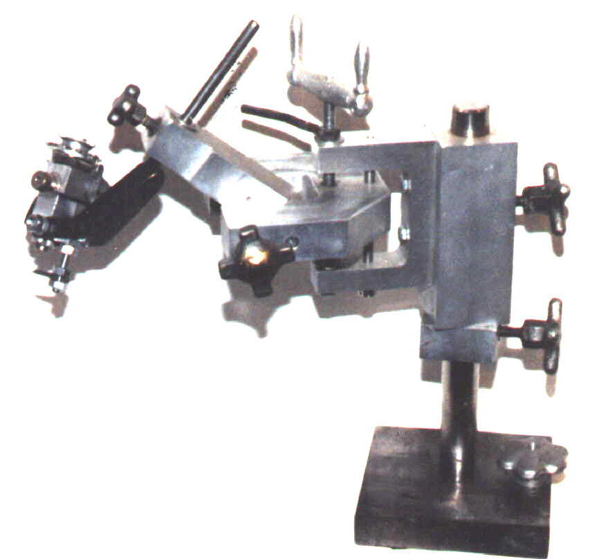
The unmounted head. All of the aluminum stock used in the actual
head
is 1 inch thick. The mast is 1 inch dia. steel and the base
plate is 1 inch
thick steel. It is heavy enough to stand by itself as shown
not requiring
any hold down at all. (Not in use. There it must be
clamped down)
Close up of the RayTech head and pivot yoke assy... The yoke
was constructed
from strap iron heated, bent and welded to shape.
The 5/16 dia Quill removed and shown from the protractor side.
Diamond claw clamp shown Dop left out.
The rod above the ring at top of the yoke is where any
additional weight would be applied. Weights were made of
lead "doughnuts" or washers having a hole of 5/16 in dia.
The weights
were added in increments to give more force down on the stone
and lap. Larger stones would require more force.
The yoke is made up of a pair of "U" shape lengths of 1/2 inch strap heated and bent to form a "U" shape which are then welded to each other and then welded to the quill and has a plate of brass or steel welded to the back of the upper U strap in back and to the quill rod. This will give an open box shape and extra strength to the assy. The bottom of the two (and the wider U ) is set onto either side of the RayTech head, mounted in reverse direction of the normal RayTech fashion. It is held in place by the pivot pin and the Protractor mounting screw on one side and the pivot pin only on the other side.
Remember: It is not shown here but this gives double the strength
and is not just one
piece of strap. That would be too flimsy to ever work.
There are several
views of the head which will show both sides of the index assy...
With that you
should be able to see that there are two side straps which are made
up by the two "U" straps. By the way the upper strap tapers into
a smaller bend at the apex or closed end of that "U".
The pivot pin is a 1/4 dia bolt with thds. on the end only. Use care not to tighten this bolt and nut too far as you must be able to pivot the head at this point.
It would be a good idea to use a locking nut such as a "Nylock" type nut.
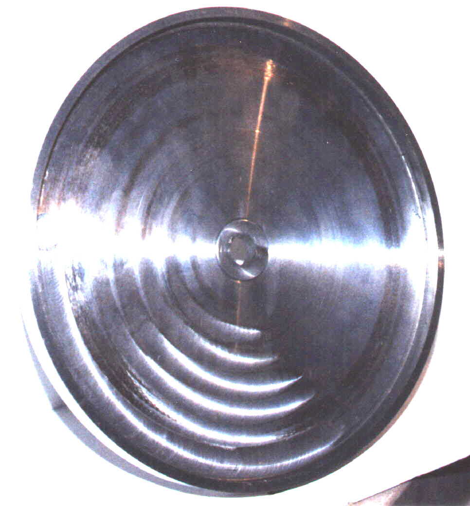
Detail of the hogged out safety lap.
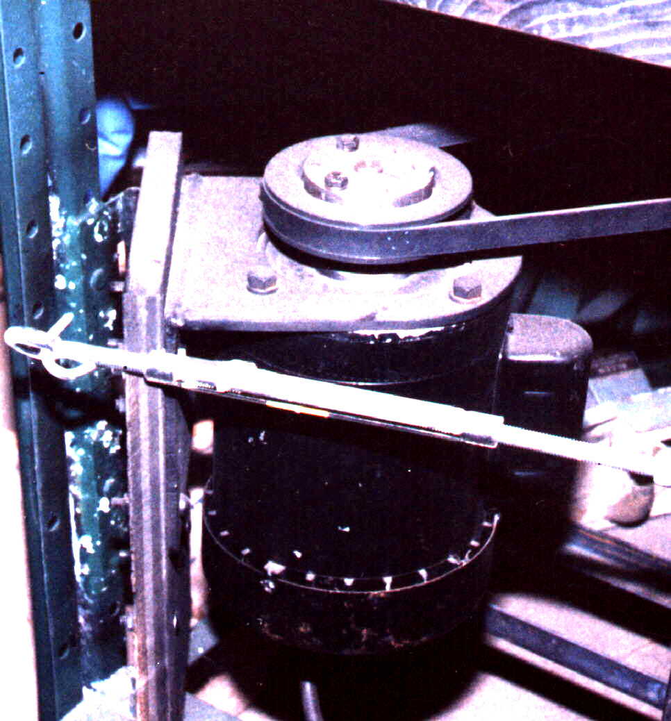
Motor and turnbuckle. The pulleys are the three part bolted
type.
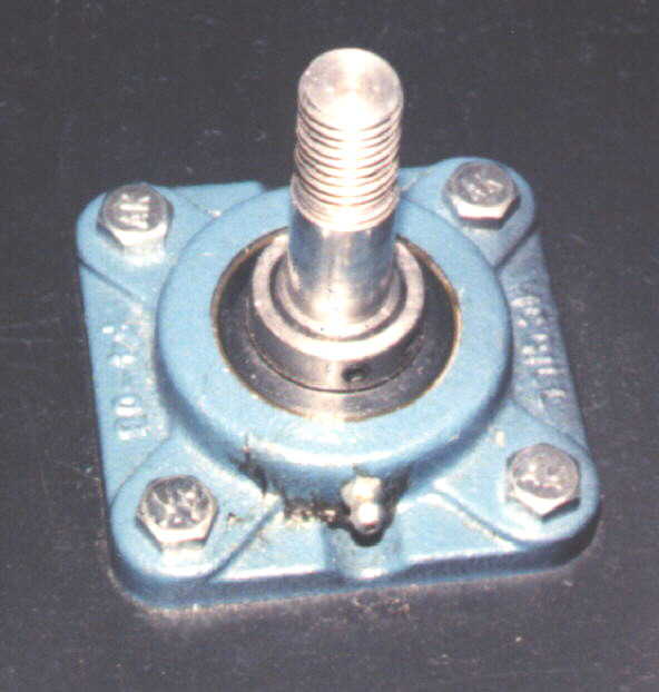
The top bearing assy. with the drive shaft shown installed.
The drive shaft is 1 inch dia turned down to fit the 3/4 bearing
and further
turned to 22 mm to fit the lap.
Note the grease fitting. This is a must.

Drive shaft shown with the step down pulley. The lower
bearing assembly is
the same kind used on the top but is mounted on a pair of angle
iron rails with
slotted holes so that the shaft can be adjusted for perpendicular.
It too has
a grease fitting. Both top and bottom bearings must be high
speed type and they
still will be very hot after running. You should only use
the best components that
money can buy.
Try the following link to see what another home brew facet machine
looks like.
This one is not for diamond but is strong enough built that with
a few modifications it would work very well in Diamond cutting.
Jon also has links to other facet related sites as well as some good joke pages. :-)
Jon Rolfe: Home made facet machine. How to do it his way. http://www.gearloose.com/
Lindsay Publications: Technical books and free catalog. http://www.lindsaybks.com